Cooling Tower Systems
COOLING TOWER SYSTEMS
Cooling tower systems range in size and purpose from dealing with air conditioning in hotels to cooling power stations. However, they all perform the same basic task: they take heat from somewhere it is not wanted and dump it into the atmosphere. To do this they use water, for two main reasons:
- Water is abundant.
- Water is very good at storing heat compared to other substances.
If we are using water to cool something down, that means heat is being transferred from that something to the water, i.e. the water is being heated. Whenever water is heated, there are likely to be problems with limescale.
These are the basic principles of a cooling tower system and apply to almost every cooling tower in operation.
- Cooling towers keep a heat source cool by evaporating water.
- Heat is transferred to the tower water in a heat exchanger.
- Problems: limescale in heat exchangers, bacteria and/or algae in the tower water.
- Blow-down, filtration and a chemical regiment are normally required for the tower to run efficiently.
- Maintenance is a necessary process for optimal operation.
We now briefly note some of the terms commonly used in reference to cooling towers.
- Air Inlet and Outlet – The points at which air enters and leaves the tower.
- Blowdown – Water is discharged from the system to control concentrations of salts or other impurities in the circulating water.
- BTU (British Thermal Unit) – The amount of heat gain (or loss) required to raise (or lower) the temperature of one pound of water one degree F.
- Capacity – The amount of water (GPM) that a cooling tower will cool through a specified range, at a specified approach and wet-bulb temperature.
- Casing or shell – This is the structure that supports the rest of the components.
- Cold Water Temperature – Temperature of the water leaving the collection basin, exclusive of any temperature effects incurred by the addition of make-up and/or blowdown.
- Distribution System – Those parts of a tower beginning with the inlet connection which distribute the hot circulating water within the tower to the points where it contacts the air for effective cooling. May include headers, lateral branch arms, nozzles, distribution basins, and flow-regulating devices.
- Drift Eliminators – An assembly of baffles or labyrinth passages through which the air passes prior to its exit from the tower, for the purpose of removing entrained water droplets from the exhaust air.
- Drift Loss – The water that leaves the cooling tower as droplets of water and typically equates to .3% of the circulating water in a tower without drift eliminators. Approximately .005% with drift eliminators. Additional water is used in a tower through evaporation.
- Dry-Bulb Temperature – The temperature of the entering or ambient air adjacent to the cooling tower as measured with a dry-bulb thermometer.
- Fan in mechanical Draft Tower – A fan is provided to move the required amount of air through the water to be cooled.
- Fill – That portion of a cooling tower that constitutes its primary heat transfer surface. Sometimes referred to as “packing”.
- Fill Deck – One of a succession of horizontal layers of splash bars utilized in a splash-filled cooling tower. The number of fill decks constituting overall fill height, as well as the number of splash bars incorporated within each fill deck, establishes the effective primary heat transfer surface.
- Forced Draft – Refers to the movement of air under pressure through a cooling tower. Fans of forced draft towers are located at the air inlets to “force” air through the tower.
- Heat Load – Total heat to be removed from the circulating water by the cooling tower per unit time.
- Induced Draft – Refers to the movement of air through a cooling tower by means of an induced partial vacuum. Fans of induced-draft towers are located at the air discharge to “draw” air through the tower.
- Louvers – Blade or passage-type assemblies installed at the air-inlet face of a cooling tower to control water splash out and/or promote uniform airflow through the fill. In the case of film-type crossflow fill, they may be integrally molded to the fill sheets.
- Recirculation – Describes a condition in which a portion of the tower’s discharge air re-enters the air inlets along with the fresh air. Its effect is an elevation of the average entering wet-bulb temperature compared to the ambient.
- Riser – Piping which connects the circulating-water supply line, from the level of the base of the tower or the supply header, to the tower’s distribution system.
- Sump – A depressed chamber either below or alongside (but contiguous to) the collection basin, into which the water flows to facilitate pump suction. Sumps may also be designed as collection points for silt and sludge to aid in cleaning.
- Cooling Tower Tonnage: Cooling towers are not the typical 12,000 BTU/Hr/ton (The amount of BTU it takes in one hour to form one ton of ice) they are 15,000 BTU/Hr/ton. The added 3,000 BTU is for removing the Chiller compressor heat. So, when a tower manufacturer says the tower is rated at 3 tons, they mean 3 X 15,000 = 45,000 BTU/Hr/ton.
- Total Water Rate – Total mass flow of water per hour through the tower.
- Tower Pumping Head – The static lift from the elevation of the basin curb to the centerline elevation of the distribution system inlet plus the total pressure (converted to ft of water) necessary at that point to effect the proper distribution of the water to its point of contact with the air.
- Transverse – Pertaining to occurrences in the direction of tower width.
- Water Inlet – This is the point at which water enters the tower.
- Water Distribution System – For maximum effect, the water entering the tower must be spread evenly over the top of the packing. This is what the distribution system does. There is a variety of distribution systems used, such as sprays or “weirs” where the water spreads by gravity.
- Water Loading – Circulating water rate per horizontal square foot of the fill-plan area of the cooling tower.
- Water Rate – Mass flow of water per square foot of the fill-plan area of the cooling tower per hour. This typically equates to 3 gallons per minute per ton of cooling capacity.
- Wet-Bulb Temperature – The temperature of the entering or ambient air adjacent to the cooling tower as measured with a wet-bulb thermometer.
- Wet-Bulb Thermometer – A thermometer whose bulb is encased within a wetted wick.
In this flyover, you will see the various cooling towers in operation.
WHAT IS THE MAIN PURPOSE OF A COOLING TOWER?
The main point of a cooling tower is to cool something down. The process of cooling down requires more than just a cooling tower. The next important piece of a cooling tower system is the heat exchanger. Tube in shell exchangers are often used in larger towers. In this type of exchanger, the tower water passes through a series of pipes within a “shell” or metal casing. The heat source (the steam or water that the tower is supposed to be cooling) passes through the shell around the tubes. Alternatively, the tower water can pass through the shell, and the heat source can pass through the tubes. In either case, the scale will form on the surfaces that are in contact with the tower water.
WHAT IS A HEAT EXCHANGER?
Obviously, the name “heat exchanger” implies that there is a transfer of heat taking place. This assumption is in fact true. The heat exchanger is where water absorbs heat energy from the heat source, so the heat source is cooled, and the tower water is heated. The water is then pumped to the top of the cooling tower, where it is sprayed in a fine mist down through the tower. As the water droplets fall through the air, they are cooled (mostly by evaporation). The water collects in a pool at the bottom of the tower (a tank or sump), and from there it is then pumped back to the heat exchanger, to start the process again. In a cooling tower system, they might be using what’s called a condenser instead of a heat exchanger. So, what is the difference between a condenser and a heat exchanger?
DIFFERENCE BETWEEN A CONDENSER VS HEAT EXCHANGER?
When the heat source is steam rather than hot water, the heat exchanger is referred to as a condenser, although they are basically the same. This is because the steam is condensing back from steam to water. The same basic principles apply with both water and steam heat sources. One extra difficulty with steam sources is that due to the high temperature of the steam, the tower water can boil at certain points (called “nucleate boiling” or “kettling”). This will leave all of the dissolved minerals behind, and so it is very hard to treat water for limescale if this type of boiling occurs inside the heat exchanger.
One of the main problems is scale in the heat exchangers. As we know, scale tends to form when water is heated (as the water becomes less able to hold onto the ions) and so the heat exchangers (where the tower water is heated) are where we find the scale. This makes the cooling tower less efficient, as the scale acts as thermal insulation, making it harder for the heat to get from the heat source to the tower water.
Other significant problems are biofouling, bacteria and algae. These will often grow in the tower pool, which is a warm, stagnant body of water and therefore ideal for the growth of micro-organisms. Both limescale and biofouling are commonly dealt with by the addition of chemicals (antiscalant and disinfectant). These are costly, need continual replacement, and can harm the environment.
WHAT IS BLOWDOWN? WHY IS IT NECESSARY IN A COOLING TOWER?
As the water is gradually evaporating to cool down, it gets more and more concentrated over time. The water is sprayed through the air to cool it and will pick up dust and other debris. The common way to deal with the build-up of minerals and debris in the cooling tower is to perform a blowdown (sometimes called bleed). What does blowdown mean? “Blowdown” is a term meaning that a portion of the water in the tower pool is flushed away and replaced with new water. The minerals, dirt, and suspended solids are washed away with the discarded blowdown water. This water must be replaced – this replacement water is called makeup water.
Cooling towers work much more effectively with an automatic blowdown system installed, which discards and replaces some of the water automatically whenever a certain concentration of dissolved solids is reached. Manually operated blow-down systems are not always operated optimally and can cause problems. Manufacturers will usually have recommendations about the blow-down level. Sticking to these limits will certainly be enough to ensure that there is no excessive build-up of calcium carbonate crystals. Blow-down rates can be reduced below the manufacturers’ limits from a scaling point of view (as long as a reasonable amount is still performed) but care needs to be taken as scaling is not the only potential problem with highly concentrated water. These will often be in terms of “cycles of concentration”.
WHAT DOES “CYCLES OF CONCENTRATION” MEAN?
Cycles of concentration are how many times more concentrated the tower water is than the make-up water. If no manufacturer’s instructions are given, then a safe rule of thumb is that blow down is performed often enough to keep the concentration of the water (the T.D.S.) at no higher than 2000 ppm or no more than 3-4 times that of the incoming water (for very hard water). In some situations, the water from the cooling tower is subsequently used for another purpose – for instance, in a factory the water may later be used for some industrial process, or in a hotel it may be used as “grey water,” i.e. for flushing toilets, etc.
Using HydroFLOW In these cases, as long as sufficient water is being used that the concentration of the water and the number of suspended particles do not get too high, additional blowdown will not be necessary – we are effectively already doing blowdown but just using the blowdown water for something rather than throwing it away.
IS FILTRATION NEEDED WITH A COOLING TOWER?
Filtration can also help remove the larger particles from the tower pool, which in turn reduces the amount of blowdown required. The type of filtration used in cooling towers is called side stream filtration which means that, rather than being fitted on the main pipe, the filter is fitted to a smaller side stream pipe that takes water out of the pool, filters it, and then returns it to the pool. The rate at which the water should be filtered depends on the rate it is passing through the tower – if the filtration rate is very slow, then all the water will be sent to the tower again before passing through the filter! A good rule of thumb is that the flow rate of the sidestream should be around 10% of the main flow rate.
Cooling tower systems operation is most efficient when the heat transfer surfaces are clean. However, these are dynamic systems due in part to their operating environment and because of the nature of their application. Cooling towers operate outside and therefore are open to the elements, making them susceptible to dirt and debris carried by the wind. Further, they often experience wide load variations, and their operation can be significantly influenced by the quality of the water used for makeup in the system. The combination of process and environmental factors can contribute to four primary treatment concerns encountered in most open-recirculating cooling systems: corrosion, scaling, fouling, and microbiological activity. These treatment concerns are interrelated such that reducing one can have an impact on the severity of the other three.
Sidestream filtration systems reduce suspended solids and debris in the system cooling water, which leads to less fouling in the system. Decreasing suspended solids can also help reduce biological growth in the system because suspended solids are a good source of food for microbiological organisms. Decreasing biological growth in turn helps to reduce microbiologically influenced corrosion. In addition, scaling can be reduced from sidestream filtration by limiting fouling and corrosion byproducts which can also contribute to scale formation on the heat exchange surfaces. Effectively managing these conditions can optimize system performance, often resulting in moderate to significant energy and water savings.
Full flow and side stream filtration are the two most common methods used to filter the water that is pumped into the circulation systems. Full flow filtration uses a filter installed after the cooling tower on the discharge side of the pump. This filter continuously filters all of the recirculating system water in the system. Inherently, the filter must be sized to handle the system’s design recirculation rate. Sidestream filtration, on the other hand, continuously filters a percentage of the flow instead of the entire flow. It can be a cost-effective alternative to full flow filtration that can easily improve the water quality to reduce water consumption and ensure the efficiency of the cooling systems. And unlike full flow filtration, side stream filtration systems can be cleaned while the cooling systems are online, avoiding the need for planned downtime.
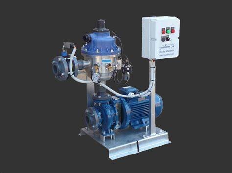
Example of a side stream filtration system.
Side stream filtration systems continuously filter a portion of cooling water to remove debris and particles. Filtered water is then pumped back into the main condenser line through a nozzle or returned to the cooling tower basin (called the sump). These systems remove suspended solids, organics, and silt particles for a portion of the water system on a continuous basis, reducing the likelihood of fouling and biological growth, which helps to control other issues in the system such as scaling and corrosion. This improves system efficiency and often reduces the amount of water rejected from the system.
There are a variety of filter types, which generally fall into four basic categories: screen filters, centrifugal filters, sand filters, and multi-media filters. Side stream filtration requires a minimum supply pressure to account for the inherent differential pressure drop across the filter. This typically ranges from 20 to 30 psi. All side stream filters have a maximum working pressure; sand filters have a threshold of 80 psi, while mechanical filters, such as screen filters, can operate up to 150 psi. Systems require the cleaning of filters or holding chambers to remove debris and particles that are trapped in filters. Filters are rated by the size of particles that can be removed, measured in microns. Suspended solids in cooling towers typically range in size from 1 to 50 microns. In general, 90% of the particles in cooling towers are smaller than 10 microns.
However, for mechanical filtration, the smaller numbers of larger particles are of more concern than the large number of smaller particles which are often bacteria removed by disinfection rather than filtration, or micron and sub-micron sized suspended solids which can be treated and removed by chemical treatment. Side stream filtration systems are generally sized to filter from 3 to 10% (up to 20%) of the overall system flow. Filters are selected based on the percent of flow that the side stream filtration system is designed to handle. For example, in a cooling system with a recirculation rate of 1500 GPM, a filtration system sized to handle 10% of the recirculation rate would be sized to handle 150 GPM.
Side stream filtration in conjunction with a HydroFLOW unit has shown a remarkable increase in water and energy savings. The reason is that HydroFLOW will render the calcium carbonate harmless and take its ability to attach to surfaces away. This effect will allow you to increase the cycles of concentration. Obviously, this will cause an increase in TSS and a side stream filter will help remove those harmless particles thus reducing the need to bleed the system and use more makeup water.
CHILLER VS COOLING TOWER
An important component of a cooling tower loop is called a chiller. Most people think that the cooling tower is solely responsible for providing the cooling necessary in an HVAC system. This isn’t true. The Chiller is a very important component and it’s often overlooked when it comes to optimizing a cooling system.
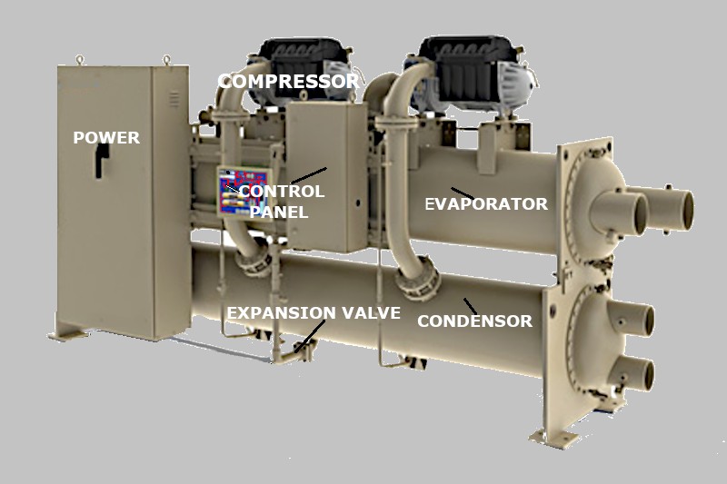
WHAT ARE THE MAIN COMPONENTS OF A CHILLER?
Compressor
The compressor creates a pressure difference to move the refrigerant around the system. There are various designs of refrigerant compressors, the most common being the centrifugal, screw, scroll and reciprocating type compressors. Each type has its own pros and cons. It is always located between the evaporator and the condenser. It’s usually partly insulated and will have an electrical motor attached as the driving force, this will be either mounted internally or externally. Compressors are easy to identify when operational because of the noise they emit.
Condenser
The condenser is located after the compressor and before the expansion valve. The purpose of the condenser is to remove heat from the refrigerant which was picked up in the evaporator. There are two main types of condensers, air-cooled and water-cooled.
Water-cooled condensers will repetitively cycle “Condenser water” between the cooling tower and the condenser, the hot refrigerant which enters the condenser from the compressor will transfer its heat into this water which is transported up to the cooling tower and rejected from the building. The refrigerant and the water do not mix they are kept separated by a pipe wall, the water flows inside the pipe and the refrigerant flows on the outside.
Expansion valve
The expansion valve is located between the condenser and the evaporator. Its purpose is to expand the refrigerant reducing its pressure and increasing its volume which will allow it to pick up the unwanted heat in the evaporator. There are many different types of expansion valves, the most common is the thermal expansion valve, the pilot-operated thermal expansion valve, the electronic expansion valve, and the fixed orifice expansion valve.
Evaporator
The evaporator is located between the expansion valve and the compressor, its purpose is to collect the unwanted heat from the building and move this into the refrigerant so that it can be sent to the cooling tower and rejected. The water cools as the heat is extracted by the refrigerant, and the “chilled water” is then pumped around the building to provide air conditioning, This “Chilled water” then returns to the evaporator bringing with it any unwanted heat from the building.
Power and Controls unit
The Powerbox and controls unit is typically mounted on the chiller. Its purpose is to monitor the various aspects of the chiller’s performance and control these by making adjustments. The controls unit will generate alarms for the engineering teams and safely shut the system down to prevent damage to the unit. BMS connections are also usually present to allow remote control and monitoring.
Common Chiller Terminology
Chiller Tonnage – One ton of cooling is the amount of heat absorbed by one ton of ice melting in one day, which is equivalent to 12,000 BTUs per hour, or 3.516 kilowatts (kW) (thermal). Chiller performance is certified by the Air-Conditioning, Heating, and Refrigeration Institute (AHRI), a manufacturer trade organization, according to its Standard 550/590: Performance Rating of Water-Chilling Packages Using the Vapor..
Compression Cycle – Two efficiency metrics are commonly used for water-cooled chillers: full-load efficiency and part-load efficiency.
Full-load efficiency – The efficiency of the chiller at peak load and at AHRI standard conditions is measured in kilowatts per ton (kW/ton). A lower kW/ton rating indicates higher efficiency.
Part-load efficiency – The efficiency of the chiller at part load is measured by either integrated part-load value (IPLV) or nonstandard part-load value (NPLV), depending on the particular AHRI part-load test conditions. Both give the efficiency of the chiller using a weighted average formula referencing four operating load points (100 percent, 75 percent, 50 percent, and 25 percent) and are expressed in kW/ton.
Reduction in water consumption: Demand for makeup water in cooling towers is decreased with an increase in the system’s cycles of concentration. Essentially, higher cycles of concentration mean that water is being recirculated through the system longer before blowdown is required. Less blowdown reduces the amount of makeup water required in the system, resulting in water savings. HydroFLOW has proven that it will increase the cycles of concentration. Nellis Airforce base installed a HydroFLOW device and ran their cooling tower up to 14,000 μS and saw no significant scale buildup.
Reduction in energy consumption: HydroFLOW reduces the likelihood of scale and fouling on the heat exchangers. Even the smallest layer of scale or fouling on heat exchange surfaces can reduce the rate of heat exchange, forcing the system to work harder to achieve the required cooling.
Reduction in chemical use: HydroFLOW renders the suspended particles into harmless TSS and interferes with biofilm so that can no longer attach to surfaces, reducing the need for additional chemical treatment such as dispersants and biocides.
Lower maintenance cost: Traditionally, cooling towers are cleaned by draining the tower and having the sediment removed mechanically or manually from the basin or sump. Cooling systems that are cleaned via side stream filtration routinely provide longer periods of continuous operation before being taken offline for required maintenance.
Improvement in productivity and reduction in downtime: When a cooling system is fouled or has scale buildup, production may be slowed due to inefficient heat exchange equipment. In some cases, the cooling system and heat exchange equipment may need to be taken offline for repairs, decreasing production. HydroFLOW will reduce the need for this.
Control of biological growth: Biological growth control and reduction can mitigate potential health risks. HydroFLOW has shown that it can improve biological control in a recirculating loop.
Sources:
https://www.towercomponentsinc.com/cooling-tower-basics-misc-terms-glossary
https://theengineeringmindset.com/chillers-main-components/
https://www.energy.gov/sites/prod/files/2013/10/f3/ssf_cooling_towers.pdf
Related article: